‘Foundation’ Tag

Sinkhole from Sewer Failure

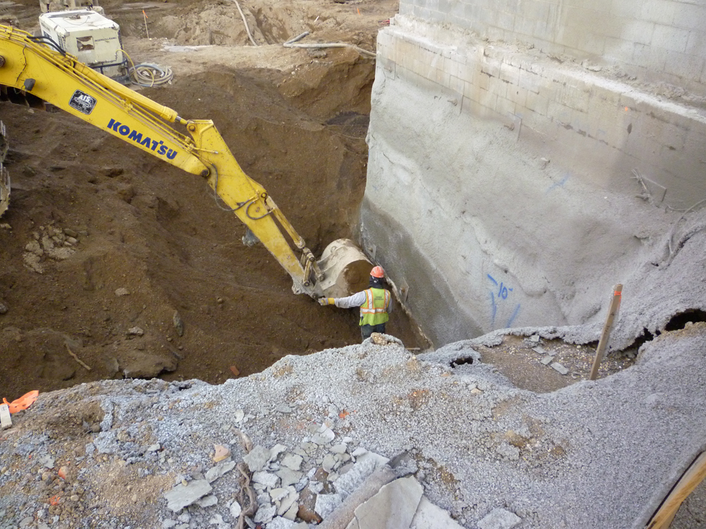
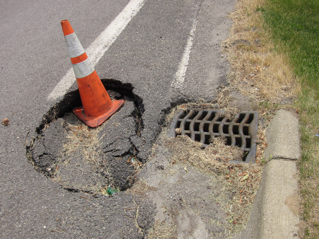
Photo Credit: Karl Jansen

This is a special kind of sinkhole probably caused by the failure of a storm sewer system connection. Sinkholes like this one form when and where a sewer pipe fails, allowing rainwater to wash earth material into the pipe and down the system. When the earth is washed away, the above material collapses down causing a hole to form. Due to the close proximity of this sinkhole to a catch basin, this sink hole was probably caused by a failure of the connection of the sewer pipe to the structure.

Leaning Tower of Pisa

Photo Credit: Jessie Benaglio

The Leaning Tower of Pisa in Pisa, Italy is the campanile, or freestanding bell tower, of the cathedral. The tower now leans at about 3.99 degrees. The top of the tower is displaced horizontally 12 ft 10 in from where it would be if the structure were perfectly vertical. Before restoration between 1990 and 2001, the tower leaned 5.5 degrees. The work involved to stabilize the tower was to extract 70 tons of earth from the northern side to encourage the tower to right itself which corrected the tower in a more upright position. The foundations only extend 3 meters below the surface. This was not deep enough to get past the soft soil. Hi-tech monitors are embedded in soil beneath its foundations and in the tower itself now show that it has stopped moving completely.

Foundation Excavation

Photo Credit: Alex Mead

Seen above is a perfect example of building a structure right up to the property line. This close quarter construction is common in urban areas and produces challenges for engineers and construction crews. As seen here, special consideration must be taken not to disturb the foundation of the adjacent building to the construction site. In order to ensure this a worker carefully directs the operator of the excavator using hand signals to be sure the foundation is not damaged by an impact from the bucket.

Large Bridge Pier with Bumpers

Photo Credit: Alex Mead

Seen here are two piers of the I-75 bridge over the Rouge River in Detroit, Michigan. The four columns support the entire weight of the bridge above and carry the load to the foundation under the surface of the water. As a result the piers need to be protected from potential impacts with vessels traveling on the water. To protect the piers engineers design barriers made of numerous logs driven into the bottom of the river bed. These barriers are then bound together with loops of steel cable. By binding the logs together the strength of the barriers greatly increases.

Suspension Bridge Cable Embankment

Photo Credit: Alex Mead

Seen here is the cable anchorage for the Ambassador Suspension Bridge over the Detroit River. This large mass of concrete is designed to deliver the opposing forced on the main cables of the bridge after they have passed over the towers. In the concrete mass the seemingly large single cable actually breaks apart into the smaller cables it is made of for anchoring purposes. The length of each cable embedded in the concrete is very important to prevent pull out of the cables and is calculated according to reinforced concrete code ACI 318.

Concrete Screeding and Pouring

Photo Credit: Alex Mead

Seen here is a concrete pour crew in the middle of placing a mat foundation. The process that is happening here is the beginning of leveling the slab of concrete to the final depth. The tool the man in maroon is using is a called a screed and is basically a gas powered leveler. The two workers behind the screed move excess concrete out of the way and add concrete to areas that are lacking to allow the screed to make a relatively flat surface. Other finishing methods are then used to make a final slab that is within a tolerance of the specified depth.

Wall Crack

Photo Credit: Nathan Shoemaker

Pictured above is a floor to ceiling crack in a masonry wall. Cracks like this can be seen in many buildings where differential settlement is occurring. Differential settlement is caused by a combination of weak or erodible soil, poor foundation design, and sometimes seismic loading of the sub-grade of the building.

Foundation Tieback Placement

Photo Credit: Alex Mead

Featured in this photograph is a worker placing tiebacks for an auger cast retaining wall system. Such retaining wall systems are designed to resist all the lateral loads imposed by the sides of an excavation. To place tiebacks the worker first drills into the earth behind the wall using the machine shown, and secures cables with grout in the hole. After the grout has cured and the cables are secure they are pulled tight using jacks and fastened to the wall to hold it in place. Excavation then continues deeper until the next layer of tiebacks is needed. The process is then repeated until the desired depth of the excavation is reached.

Reinforcing Steel for Foundation

Photo Credit: Alex Mead

What you are looking at is the steel that is in all the reinforced concrete structures around you. The large number of bars that you see are meant to hold the tension force in the foundation of this underground parking structure. One of the main costs in reinforced concrete construction is the labor to place all the resteel where it is needed. As you can see from this photo the number of resteel bars is staggering. Rest assured though, each bar has its proper place calculated by a competent structural engineer!