‘Structural’ Category

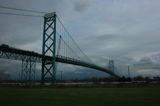
Ambassador Bridge – Suspension Bridge

Photo Credit: Alex Mead

Seen above is the Ambassador Bridge connecting Detroit, MI, USA to Windsor, Ontario, Canada. It is a standard suspension bridge with two anchorages, two towers, and two main cables. A unique feature of this bridge is it is privately owned and an international border crossing. It is owned by Michigan billionaire Manuel Moroun and has lead to many controversies as this bridge is the only connection for many miles which commercial truck traffic can cross between the two countries.
Concrete Bridge Substructure

Photo Credit: Karl Jansen

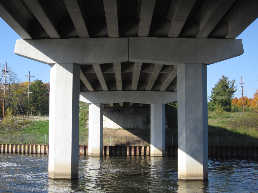
This is the underside of a concrete bridge. Technically, this is known as the substructure, or the part of the whole structure that supports the superstructure, or the roadway in this case. You can see nicely the beams and girders that run laterally and longitudinally under the bridge superstructure, and the massive columns that extends vertically down to the ground to provide the support. The substructure is an important element of every bridge.

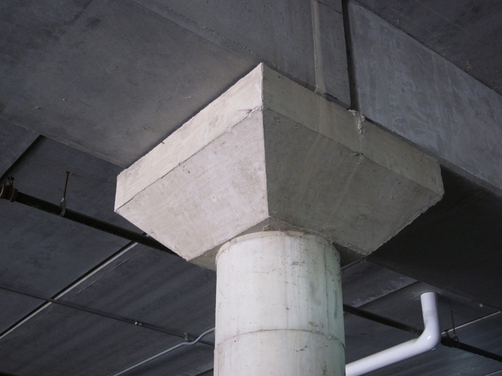
Flared Concrete Column

Photo Credit: Karl Jansen

This is a great example of a flared concrete column. As you can see, the top of the circular column which supports the above structure is flared in a square section. This allows for a wider (and less dense) distribution of loads from above being transferred to the column.

Failing Infrastructure

Photo Credit: Karl Jansen

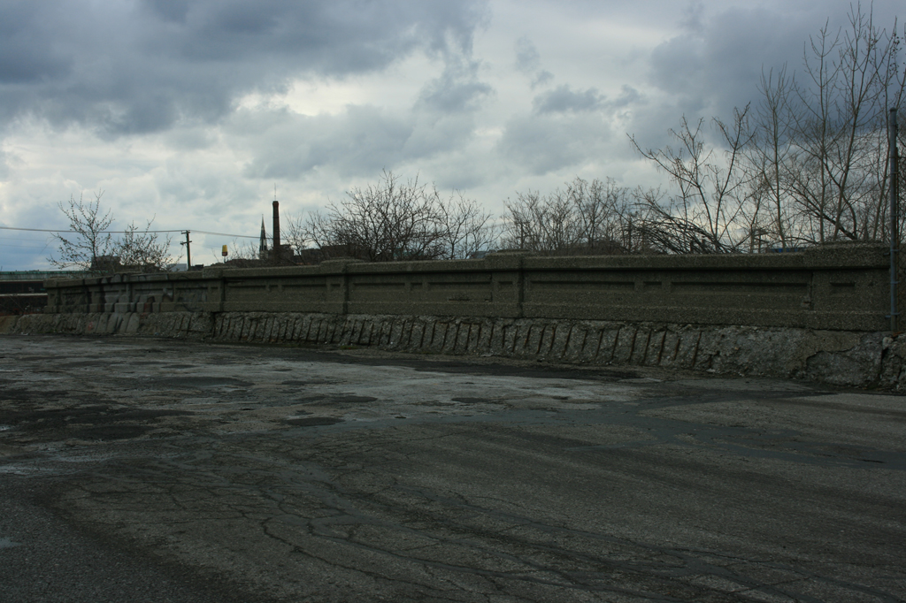
This is the infamous Stadium Blvd Bridge in Ann Arbor, MI. For the past several years, this bridge has literally been falling down, waiting on funds for a rehabilitation project. What you see on the near side of the bridge is an exposed beam, which used to be the south side of the bridge. Last year, the south half of the bridge was removed for public safety reason, because officials were worried “football size” chunks of concrete would fall on a car or pedestrian. This fall, the City of Ann Arbor with its secured funding will finally undertake this long overdue project.

Exposed Rebar on Bridge

Photo Credit: Alex Mead

Seen here is an example of the crumbling infrastructure often reported by the media. As can be seen in this photograph of the top side of a bridge, all the rebar of the side barrier is exposed along the roadway. This is especially bad because when salt is applied during the winter to prevent ice buildup on the roadway, the rebar is eroded even faster than it would be if it were only exposed to air and water. This is due to the chlorides in the salt that become active when dissociated in water.

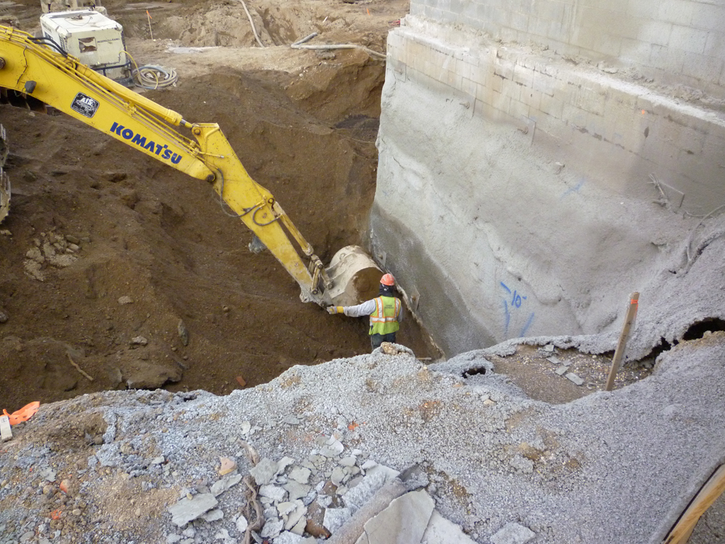
Foundation Excavation

Photo Credit: Alex Mead

Seen above is a perfect example of building a structure right up to the property line. This close quarter construction is common in urban areas and produces challenges for engineers and construction crews. As seen here, special consideration must be taken not to disturb the foundation of the adjacent building to the construction site. In order to ensure this a worker carefully directs the operator of the excavator using hand signals to be sure the foundation is not damaged by an impact from the bucket.

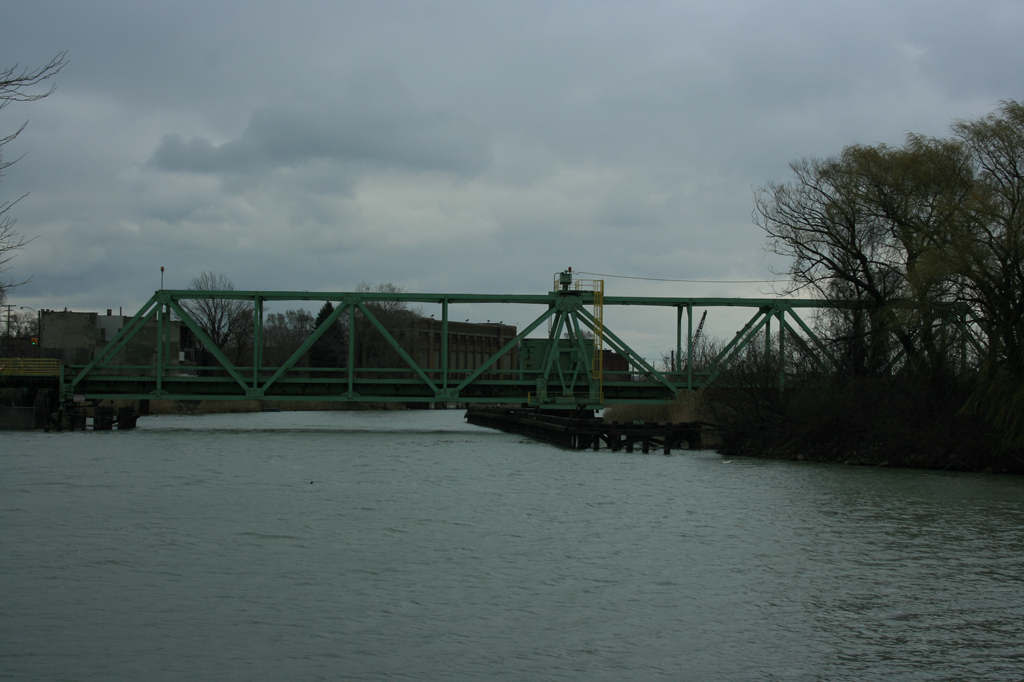
Swing Bridge

Photo Credit: Alex Mead

Seen above is a swing bridge over a small river near Detroit, MI. The concept of a swing bridge is similar to a draw bridge in that the bridge is movable to allow traffic to pass through the area it spans. This allows a smaller bridge to be built than would otherwise be necessary for height clearance purposes. The swing bridge operates by rotating around the central pivot of the span to clear the area above the water surface to allow vessels to pass. The bridge is currently in the “closed” position and would be perpendicular to the screen if it were rotated to the “open” position to allow traffic to pass.

Reduced Steel Beam Section

Photo Credit: Alex Mead

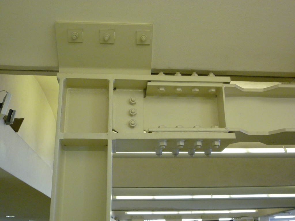
Seen here is a full moment connection between a beam and a column. Note the numerous welds, bolts, and stiffener plates required to get a full moment transfer from the beam to the column. The careful observer will also notice in this example that the beam is actually part of a plastic hinge inducing connection. This is evident by the reduced flange in the beam on the right side of the picture. This reduced section is purposely placed here to force the beam to form a plastic hinge in this location and draw the damaging plastic behavior into the beam away from the column. This connection is part of a strong column, weak beam design approach and allows the structure to absorb substantial amounts of energy in an event such as an earthquake without failing in a story collapse mechanism.

Large Bridge Pier with Bumpers

Photo Credit: Alex Mead

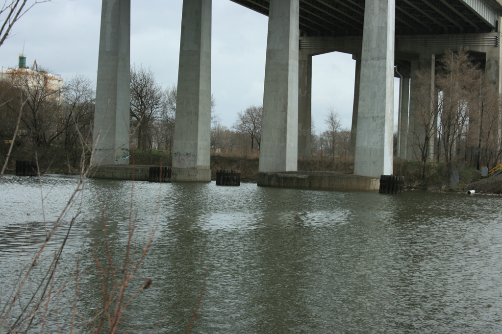
Seen here are two piers of the I-75 bridge over the Rouge River in Detroit, Michigan. The four columns support the entire weight of the bridge above and carry the load to the foundation under the surface of the water. As a result the piers need to be protected from potential impacts with vessels traveling on the water. To protect the piers engineers design barriers made of numerous logs driven into the bottom of the river bed. These barriers are then bound together with loops of steel cable. By binding the logs together the strength of the barriers greatly increases.