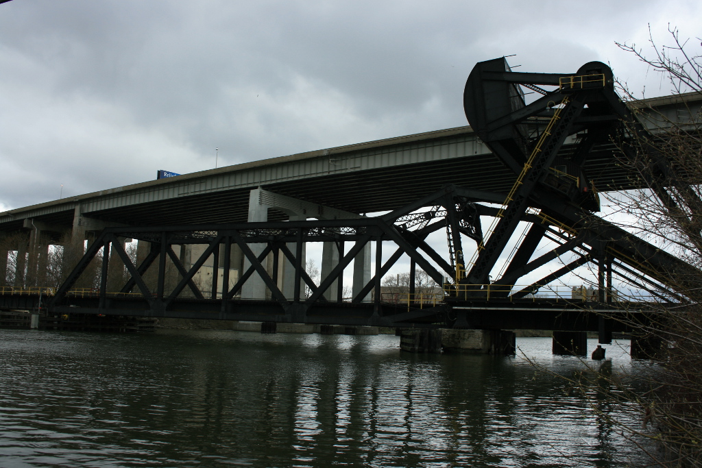
Photo Credit: Karl Jansen
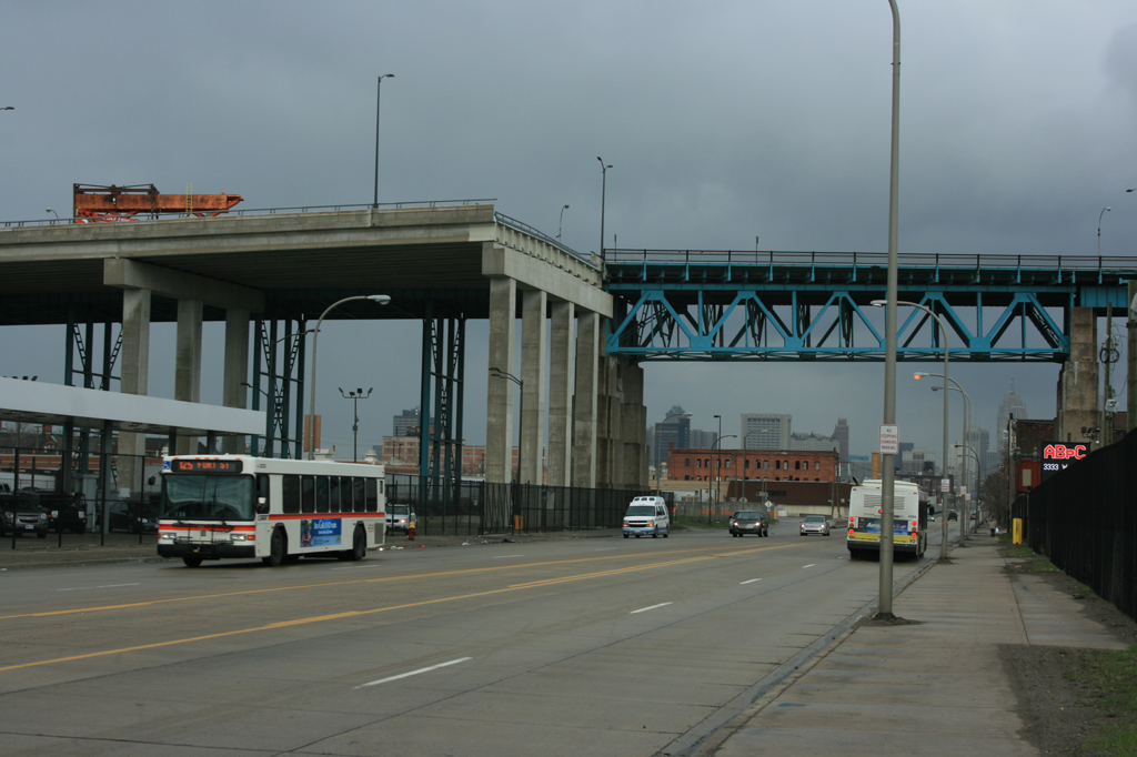
This is a roller support. It is one of the most common types of structural supports used by civil engineers. This roller support allows for the supported structure to move horizontally, while the upward reaction force prevents the structure from falling down. The single reaction force is always perpendicular to the surface and in the direction away from that surface (normal). This type of support is often found at one end of a long bridge, allowing the bridge to expand and shrink with the natural temperature changes.