‘Geotechnical’ Category

Auger Cast Pile Drill Rig

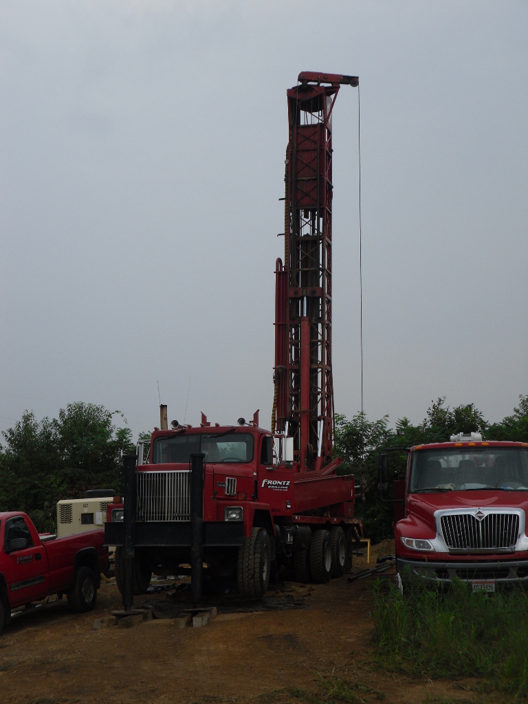
Photo Credit: Alex Mead

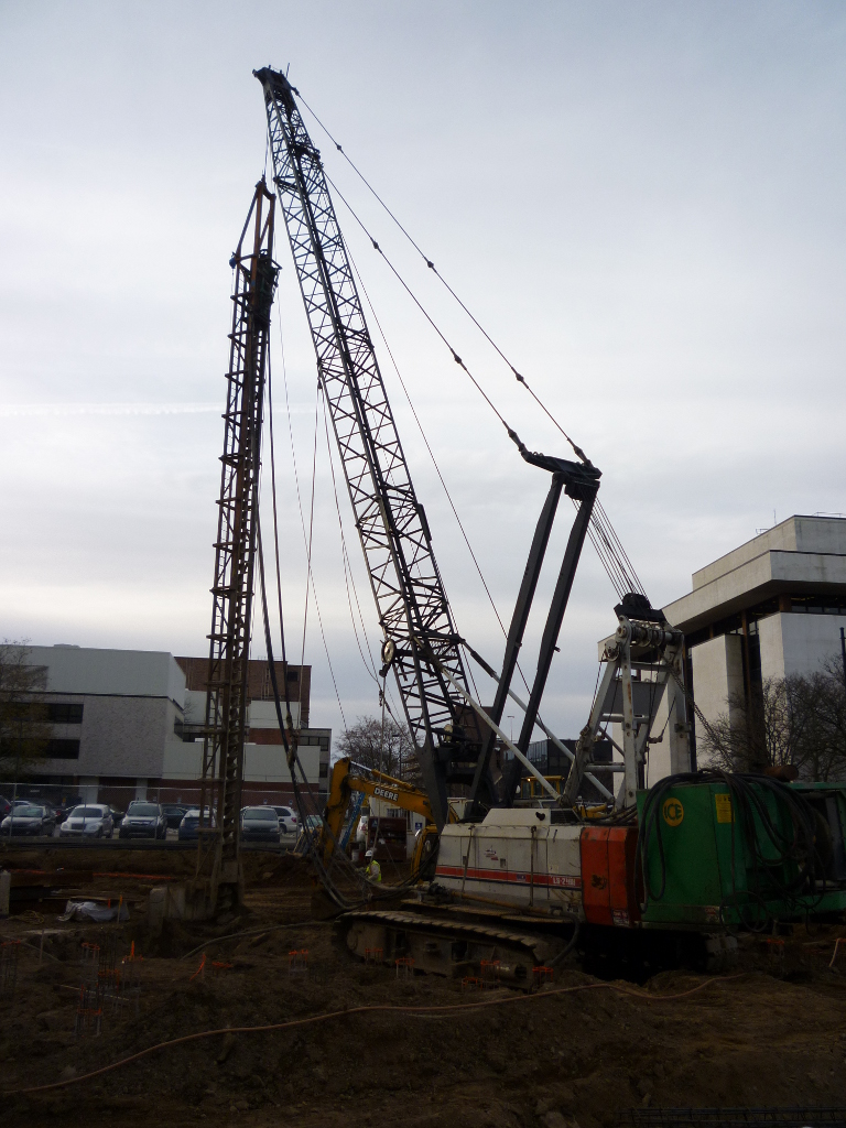
Pictured above is a drill rig used for constructing auger cast piles. On this machine a few features are very obvious that make it different than a traditional boom-lattice crane. First, the large green box on the back is an engine that powers the auger. The auger, encased in the frame hanging on the front of the crane, is then used to excavate the soil where the piles will be poured. Once the auger reaches the desired depth, concrete is pumped through the auger like a straw to fill the hole as it is pulled out. A resteel cage can then be lowered into the hole to add tensile strength to the auger cast pile.

Water-Rotary Rock-Core Rig

Photo Credit: Nathan Shoemaker

This drill rig is used to core rock, and water is used to keep the bit cool, clean and lubricated. Rock coring is used for geotechnical and hydrological investigation as well as for well drilling in certain instances and also oil exploration.

Landslide Cleanup

Photo Credit: Nathan Shoemaker

Pictured above is the cleanup of a roadway after a landslide. This particular landslide was caused by heavy rains and steep cuts in the soil material in concert with a relatively weak soil. You can see the head-scarp, the area where the failure beginnings, is clearly distinguishable.

Wall Crack

Photo Credit: Nathan Shoemaker

Pictured above is a floor to ceiling crack in a masonry wall. Cracks like this can be seen in many buildings where differential settlement is occurring. Differential settlement is caused by a combination of weak or erodible soil, poor foundation design, and sometimes seismic loading of the sub-grade of the building.

CPT Rig

Photo Credit: Nathan Shoemaker

Pictured above is a Cone-Penetration-Test(CPT) Rig. CPTs are used for geotechnical site-investigations and can help determine the soil type, soil layer thickness, relative strength of the soil, and pore water pressure among other things. This information is then used to determine how structures must be built on the site. The CPT test is done using a small diameter cone that is hydraulically pushed at a constant displacement; the cone is configured with multiple transducers to measure tip resistance, sleeve (friction) resistance, and pore-water pressure.